Power Vented Gas Water Heater Maintenance
KEEP YOUR UNIT RUNNING EFFICIENTLY AND LASTING LONGER
Gas water heaters were created to last for 8-12 years. But here’s the catch, to keep your water heater lasting this long, you will have to perform routine maintenance checks to keep it running in optimal condition. Of course, the maintenance steps all depend on your unit, model, location and application of your specific water heater and you should refer to your unit’s specific user manual for proper maintenance protocol. However, following these general maintenance tips will help your unit stay in solid condition and last longer.
The following information is provided in the Installation and Operating Manual for Residential Gas Water Heaters from AO Smith for the ProLine(R) XE Power Vent. Always refer to the installation guide before performing any maintenance checks. If the information in these instructions is not followed exactly, a fire or explosion may result causing property damage, personal injury or death.
You can find a list of Residential Gas water heaters under the ProLine(R) models here.
General Upkeep
Make it a habit to look around the heater, the vent piping, and the hot and cold water pipes. Do not allow any material to be piled up against the heater. Do not place any object on top of the vent pipes.
Every 3 - 6 months or as necessary:
Clean lint from blower, top of heater
Once per year:
Inspect the Vent System
Burner Operation and Inspection
Combustion Chamber for scaling or sooting
Temperature-Pressure Relief Valve Test
Anode Rod Inspection
Flush a pail of water from the heater drain valve, once per year
If any deficiencies or abnormalities are encountered during these inspections call a qualified service technician.
VENTING SYSTEM INSPECTION
WARNING! BREATHING HAZARD - CARBON MONOXIDE GAS
Flue gases may escape if vent pipe is not properly connected.
Be alert for obstructed, sooted or deteriorated vent system to avoid serious injury or death.
Do not store corrosive chemicals in vicinity of water heater.
Chemical corrosion of flue and vent system can cause serious injury or death.
Analyze the entire vent system to make sure that condensate will not become trapped in a section of vent pipe and therefore reduce the open cross sectional area of the vent.
At least once a year a visual inspection should be made of the venting system. You should look for:
Obstructions which could cause improper venting. The combustion, dilution and ventilation air flow must not be obstructed.
Damage or deterioration which could cause improper venting or leakage of combustion products.
Be sure the vent piping is properly connected to prevent escape of dangerous flue gasses which could cause deadly asphyxiation. Obstructions and deteriorated vent systems may present serious health risk or asphyxiation.
Chemical vapor corrosion of the flue and vent system may occur if air for combustion contains certain chemical vapors. Spray can propellants, cleaning solvents, refrigerator and air conditioner refrigerants, swimming pool chemicals, calcium and sodium chloride, waxes, bleach and process chemicals are typical compounds which are potentially corrosive.
If after inspection of the vent system you found sooting or deterioration, something is wrong. Call the local gas utility to correct the problem and clean or replace the flue and venting before resuming operation of the water heater.
BLOWER MAINTENANCE
Inspect the top of the heater and around the ventilation openings of the blower motor and the rear blower dilution air intakes for any lint and dust that may have accumulated. Depending on the location of the heater, significant quantities of lint may accumulate. The lint may obstruct the free flow of air to the motor, and cause the motor and blower to run hotter than normal (see Figure 50).

To clean any dust and lint, proceed as follows:
1. Unplug the water heater.
2. Using a nylon bristled paint or toothbrush, brush away any lint. Pick up the lint with a cloth.
Better results can be achieved by using the small brush on a vacuum cleaner to remove all lint and dust which have accumulated on top of the heater, the louvres of the air intake snorkel, the motor ventilation openings and the rear blower dilution air intakes.
Important: Do not insert any foreign object into the ventilation openings of the motor.
CLEANING THE BLOWER
In dusty and contaminated air conditions, the interior of the blower and the blower wheel may require periodic cleaning. This is often indicated by nuisance failures of the air pressure switch or the high limit temperature control. A collection of dust or debris on the rear blower dilution
air intakes can also indicate reduced blower capacity. To clean the inside of the blower assembly and the blower wheel requires the removal of the blower/motor from the mounting plate located on the top of the heater. Tools required include an 11/32” nut driver, small ( 1” ) paint brush, toothbrush and vacuum cleaner.
1.Turn the thermostat on the gas control to the lowest setting. If the heater is running, wait for it to shut down (see Figure 49).

2. Turn the gas control switch to the “OFF” position.
3. Disconnect the electrical power to the water heater from the wall outlet.
4. Disconnect the vent piping from the top of the blower. Loosen the lower gear clamp that holds the rubber coupling to the blower (see Figure 50).
5. Remove and retain the (4) 11/32” nuts located on the back of the blower with the nutdriver (see Figure 43 & Figure 50).

6. Holding the blower motor and the blower housing, pull the assembly forward to disengage it from the mounting plate. The blower will still be connected to the junction box so exercise care not to stress the wiring.

7. Accessing the blower wheel through the outlet, use the paint brush to brush off the outer edge of the blower wheel to dislodge the dirt stuck on the blades and the inside of the housing. Rotate the wheel until all blades are clear. Note: The wheel is a balanced component. Do not bend, dent or distort the blades as this can upset the wheel balance and affect the blower operation. Vacuum out the loosened dirt.
8. Accessing the inside of the blower wheel through the rear of the housing, gently brush off the inside of the blades using the toothbrush. Again, take care not to distort the blades. Rotate the wheel until all blades are cleaned and vacuum the debris. Do not remove any of the balancing chips attached to the blades.
9. Inspect the flue collector hood (still attached to the heater) and vacuum out the dust and debris that may have accumulated.
10. With all parts cleaned and the blower wheel turning freely, reinstall the blower to the mounting plate aligning the (4) studs and pushing tight against the mounting plate.
11. Reinstall the (4) 11/32” nuts and tighten securely. All (4) nuts must be in place and secure to safely operate the blower.
12. Reattach the vent piping and coupling to the top of the blower, tighten the bottom gear clamp and ensure the piping is secure.
13. With all components clean and secure, reconnect the electrical power to the heater.
14. Reset the thermostat to the desired temperature setting and turn the gas control switch back to the “ON” position. Note: If the water in the heater is hot, the unit will wait to operate until there is a need for more hot water.
BURNER OPERATION AND INSPECTION
Flood damage to a water heater may not be readily visible or immediately detectable. However, over a period of time a flooded water heater will create dangerous conditions which can cause death, serious bodily injury, or property damage. Contact a qualified installer or service agency to replace a flooded water heater. Do not attempt to repair the unit! It must be replaced!
At least once a year a visual inspection should be made of the main burner and the hot surface igniter assembly for proper flame characteristics and ignition sequences. This can be done by removing the outer door and viewing the main burner operation through the viewport on the inner door (see Figure 51). The main burner should provide complete combustion of gas, ignite rapidly, give reasonably quiet operation, and cause no excessive flame lifting from the burner ports. If the proper flame characteristics are not evident (see Figure 52), make sure that the flow of combustion and ventilation air is not blocked.


You should also check for sooting. Soot is not normal and will impair proper combustion. A visual inspection of the main burner and hot surface igniter should also be done at least once a year (see Figure 51). Soot build-up indicates a problem that requires correction before further use. Turn “OFF” gas to water heater by unplugging the power cord and leave off until repairs are
made. Failure to correct the cause of the sooting can result in a fire causing death, serious injury, or property damage.
COMBUSTION CHAMBER AND BURNER CLEANING
DANGER! FIRE AND EXPLOSION HAZARD!
Do not obstruct combustion air openings at the rear of the water heater.
Do not use or store flammable vapor products such as gasoline, solvents or adhesives in the same area near water heater or other appliance.
Can cause serious injury or death.
INSTALLED IN SUITABLE AREA
To ensure sufficient ventilation and combustion air supply, proper clearances from the water heater must be maintained. See “Locating The New Water Heater” section (in the Installation and Operating Manual). Combustible materials such as clothing, cleaning materials, or flammable liquids, etc. must not be placed against or adjacent to the water heater which can cause a fire.
TEMPERATURE-PRESSURE RELIEF VALVE TEST
DANGER!
Burn hazard
Hot water discharge
Keep clear of temperature-pressure relief valve discharge
It is recommended that the temperature-pressure relief valve be checked to ensure it is in operating condition at least once a year.
When checking the temperature-pressure relief valve operation, make sure that (1) no one is in front of or around the outlet of the T&P valve discharge line, and (2) that water discharge will not cause any property damage, as water may be extremely hot. Use care when operating valve as the valve may be hot. To check the relief valve, lift lever at the end of valve several times (see Figure 53). The valve should seat properly and operate freely.
If after manually operating the valve, it fails to completely reset and continues to release water, immediately close the cold-water inlet to the water heater and drain the water heater, see “Draining And Flushing” section. Replace the T&P valve with a properly rated/sized new one, see “Temperature-Pressure Relief Valve” for instructions on replacement.

If the Temperature-Pressure Relief Valve on the water heater weeps or discharges periodically, it may be due to thermal expansion.
Note: Excessive water pressure is the most common cause of temperature-pressure relief valve leakage. Excessive water system pressure is most often caused by “thermal expansion” in a “closed system.” See “Closed Water Systems” and “Thermal Expansion” sections of this manual. The T&P valve is not intended for the constant relief of thermal expansion.
Temperature-pressure relief valve leakage due to pressure build up in a closed system that does not have a thermal expansion tank installed is not covered under the Limited Warranty. Thermal expansion tanks must be installed on all closed water systems.
WARNING EXPLOSION HAZARD!
Temperature-pressure relief valve must comply with ANSIZ21.22-CS4.4 AMD ASME code.
Properly sized temperature-pressure relief valve must be installed in opening provided.
Do not plug, block, or cap the discharge line
Failure to follow this warning can result in excessive tank pressure, serious injury or death.
DRAINING AND FLUSHING
Periodic draining and cleaning of sediment from the tank may be necessary. It is recommended that the tank be drained and flushed every 6 months to remove sediment which may build up during operation. The water heater should be drained if being shut down during freezing temperatures. See “Typical Installation” section in this manual for location of the water heater components described below.
DANGER!
Burn hazard
Hot water discharge
Keep hands clear of drain valve discharge
To Drain the Water Heater Storage Tank
1.Turn “OFF” the electrical supply to the water heater.
2. Turn “OFF” the gas supply at the Main Gas shut-off Valve.
3. Open a hot water faucet and let the hot water run until it is cool (This may take 10 minutes or longer).
Warning: Be sure the water runs cool before draining the tank to reduce the risk of scalding.
4. Connect a garden hose to the drain valve and place the other end of the hose in an adequate drain, outside, or in buckets. Note that sediment in the bottom of the tank may clog the valve and prevent it from draining. If you can’t get the tank to drain, contact a qualified person.
5. CLOSE the cold-water inlet valve to the water heater.
6. Open the drain valve on the water heater.
7. If not already done, open a hot water faucet to help the water in the tank drain faster.
8. If a large amount of sediment was present when the tank was drained, follow instructions in the “To Flush the Water Heater Storage Tank” section.
9. Close the water heater drain valve when all water in the storage tank has drained and remove the hose.
10. Follow instructions in the “Filling The Water Heater” section.
11. Follow the lighting instructions on the label or see “Lighting Instructions” to restart the water heater.
Note: If the water heater is going to remain shut down and empty for an extended period, the drain valve should be left open with hose connected allowing water to terminate to an adequate drain.
To Flush the Water Heater Storage Tank
Follow Step 1 through Step 7 in the “To Drain the Water Heater Storage Tank” section.
1.Flush the tank by opening the cold water supply valve and letting the water run until no more sediment drains from the tank.
2. Close the water heater drain valve when flushing is completed and remove the drain hose.
3. Ensure the heater is full of water.
4. Follow instructions in the “Filling The Water Heater” section.
5. Follow the lighting instructions on the label or see “Lighting Instructions” to restart the water heater.
Caution: Do not turn on power to the water heater unless the tank is full. Open a hot-water faucet and allow the water to run until the air is purged and the water flows uninterrupted from the faucet.
Important: When operating a cold tank, condensation can occur and drip on the burner. This should not be confused with a tank leak.
ANODE ROD MAINTENANCE
CAUTION: PROPERTY DAMAGE HOLD
Avoid water heater damage.
Inspection and replacement of anode rod required.
Anode Rod. The anode rod is a sacrificial metal rod that helps avoid corrosion and premature failure (leaks) in the tank. The anode rod is a consumable item. Inspect the anode rod after the first six months of operation when you drain and flush the tank. Replace the anode rod if it is substantially worn out or depleted (see Figure 54). Thereafter, inspect the anode rod annually or more frequently if needed. If you use a water softener, your anode rod will deplete faster than normal. Inspect the anode rod more frequently, replacing the anode rod if it is depleted. Once the anode rod is depleted, the tank will start to corrode, eventually developing a leak. Obtain a new anode rod from your local plumbing supplier or have a qualified person replace it. (Anode rods are a consumable item and are not covered under warranty).
Certain water conditions will cause a reaction between the anode rod and the water. The most common complaint associated with the anode rod is a “rotten egg smell” produced from the presence of hydrogen sulfide gas dissolved in the water. The removal of the anode rod requires a 1-1/16” socket.
Important: Do not operate the water heater without a functioning anode rod as this will void any warranties. A special anode rod may be available if water odor or discoloration occurs.
Note: This rod may reduce but not eliminate water odor problems. The water supply system may require special filtration equipment from a water conditioning company to successfully eliminate all water odor problems.
To replace the anode:
1. Turn “OFF” the electrical supply to the water heater.
2. Turn “OFF” the gas supply at the Main Gas shut-off Valve.
3. CLOSE the cold-water inlet valve to the water heater.
4. OPEN a nearby hot-water faucet and leave open to allow for draining.
5. Drain approximately 5 gallons of water from tank. (Refer to “Draining And Flushing” for proper procedures). Close drain valve.
6. Remove old anode rod.
7. Use Teflon® tape or approved pipe sealant on threads and install new anode rod.
8. Remove the hose and follow instructions in the “Filling The Water Heater” section.
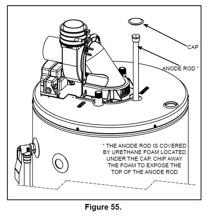
9. Follow the lighting instructions on the label or see “Lighting Instructions” to restart the water heater. See Figure 55 for anode rod location.